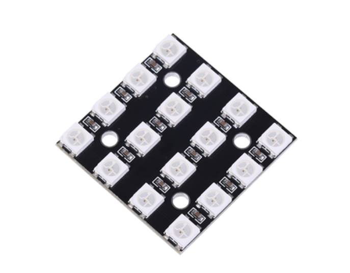
First, let's explain how it works with some basic examples, and then look at a really cool Arduino project that uses these leads -- a DIY interactive LED coffee table.
The coffee table comes with a WS2812B LED light, an infrared proximity sensor for object detection, and an HC-05 Bluetooth module for color control via a customized Android application.
This product can be purchased on the WS2812B RGB LED strip manufacturer.
Let's first take a closer look at the LED strip.
It consists of a model 5050 RGB LED light integrated with a very compact WS2812B LED driver IC.

Based on the intensity of the three red, green and blue leds, we can simulate any color we want.
The advantage of using these leds is that we can control the entire LED strip using only one pin on the Arduino development board.
Each LED has three connector interfaces at each end, two for power supply and one for data.
Arrows indicate the direction of data flow.
The data output pad of the previous LED is connected to the data input pad of the next LED.
We can cut the strip to any size we want, and we can also use wires to increase the LED distance.
As for the power supply, they work at 5V and require about 20mA per red, green and blue LED, or a total of 60mA per LED at full brightness.
Note that the 5V pin can only handle about 400 mA of current when the Arduino is powered via USB, and about 900 mA when powered using a bucket power connector.
Therefore, if you use more leads and the amount of electricity they will draw exceeds the above limits, you must use a separate 5V power supply.
In this case, you also need to connect the two ground cables to each other.
In addition, it is recommended to use a resistor of approximately 330 ohm between the Arduino and the LED light strip data pins to reduce noise on this line, and a capacitor of approximately 100uF on the 5V and ground to smooth the power supply.